Component blocks and assemblies can be used for CFD analyses to simply allow for the effect of obstructions on the airflow. However, they also allow the definition of CFD boundary attributes to enable them to act as constant temperature surfaces or heat flux sources and can also be modified to behave as non-solids to allow air to pass through them.
Note: Component blocks and assemblies defined at block level do not affect EnergyPlus simulations.
CFD attributes for component blocks are inherited down from the building level to component blocks located at both building and building block levels. CFD attributes for component blocks are accessed on the CFD model data tab.
The CFD assembly library that is provided with DesignBuilder contains a number of pre-defined assemblies that can be used to add items such as occupants, radiators and furniture. Some of these pre-defined assemblies already have CFD boundary attributes associated with them, e.g. standing occupant assemblies have a defined convective heat flux of 56W. You can also define your own assemblies for use in CFD analyses and you will find details of how to do this in the Assembly library section.
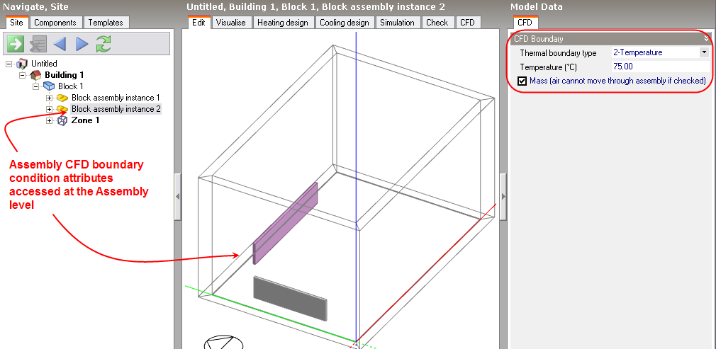
CFD attributes for component assemblies are inherited from the parent assembly to instances of the assembly at the building and building block levels. CFD attributes for assemblies are accessed from the CFD tab after moving down to an assembly instance level by clicking on it in the navigator or double-clicking on it in the Edit screen. It is important to understand that if you change an attribute for a specific instance of an assembly, the attributes will be changed for all other instances of the same assembly.
The following CFD boundary settings can be set on the CFD model data tab for both component blocks and component assemblies:
Thermal boundary type: The thermal boundary type can be set to one of the following:
If the thermal boundary type has been set to 2-Temperature, enter the temperature of the block.
If the thermal boundary type has been set to 3-Flux, enter the convective only portion of the heat emission of the block. If you know the total heat flux then you can calculate the convective part by multiplying by (1-radiant fraction). For modelling building occupants you can assume a radiant fraction of 0.5. Sources of radiant fraction data for other equipment can be found at:
Note: In cases where one or more faces of a component block are not in contact with the zone air (e.g. when the component block surface is adjacent to the floor or another component block) the total convective gain specified for the block is applied only to the surfaces in contact with the air.
Important Note: In the case of assemblies used to apply a heat flux boundary condition, the heat flux data on the CFD tab of the component blocks can be treated in one of 2 ways depending on whether or not it inherits this data from the assembly above:
a) When inheriting from the assembly above, the same heat flux data as for the parent assembly appears in blue on the CFD tab, but DesignBuilder doesn't use this directly. Instead the data is applied as if it is the total for the whole assembly and the actual value for this component block is reduced by a proportion equal to the ratio of the component volume to the volume of the whole assembly.
b) When hard set heat flux data is entered (data shown in red on the CFD tab), this is used directly in CFD calculations and spread evenly around the component block surfaces.
Determines whether or not the block will act as a physical obstruction to the surrounding flow. In some cases, it may be desirable to fix the temperature or flux of the component but allow air to pass through the block, e.g. to represent an occupancy flux throughout a large volume without needing to locate individual occupants.
The Solid cell overlap tolerance is an advanced setting that allows some control over the identification of CFD grid cells that are to be interpreted as lying within a component and to be flagged as solid in the CFD simulation (assuming the mass flag is set for the component/assembly).
The overlap tolerance is a number between 0.0-1.0 representing a fractional overlap. The algorithm used to identify solid component cells marches up through the grid in the Z-dimension, creating a slice through each component at the height of each cell centre. An intersection check is then made for the resulting polygon list with each cell rectangle in plan. If the ratio of the intersection area to the cell area is greater than the tolerance, the cell is flagged as solid.
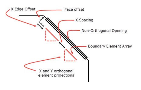
CFD ventilation boundary conditions that are not orthogonal to the grid (i.e. not aligned with the grid) require special treatment to minimise problems caused by insufficient cell numbers in the vicinity of default boundary elements which can result in the flow stalling (mass flat-lining). The ventilation boundary mechanism for non-orthogonal ventilation boundaries involves automatically creating an array of rectangular elements across the face of the boundary. The resulting array of elements are then offset from the boundary face and projected onto the orthogonal X, Y, Z planes to form the orthogonal elements.
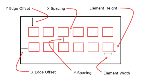
The diagrams below summarise the meaning of the various settings.
Normal View
Plan View
The following settings can be used at Building, Block and Zone levels as well as for non-orthogonal surfaces and their ventilation boundary conditions to allow hierarchical default settings to be defined.
The default value of of 1.0m means that any opening having a dimension of 1.0m or less will have one projected element (max 0.9m distance from the opening with a 0.2m offset). This usually provides reasonable results without instability.
See above for Element width.
The face offset is used to shift the ventilation boundary elements away from the parent surface into the body of the space by the defined offset distance. The reason for this setting is that in some cases, depending on the grid resolution, the algorithm that identifies solid cells can lead to a conflict between some solid cells and the boundary elements which can result in flow stalling (this was particularly a problem at the edges of full width windows which may not actually be such a problem now that we have an edge offset setting).
X-spacing is the gap between the cells in the x-direction.
Y-spacing is the gap between the cells in the y-direction.
Z-spacing is the gap between the cells in the z-direction.
The offset in the x-direction between the edge of the boundary condition and the first cell.
The offset in the y-direction between the edge of the boundary condition and the first cell.